GC Video timings
In this write up I am going to walk you guys through my research into the gc's digital video port. I wanted to understand how the vsync and hsync timing pulses get transmitted from the digital port. The official SDK documentation states "We define seven basic rendering modes for each of the three main television video modes (NTSC, PAL, M/PAL), making a total of 21 predefined rendering modes" for the developer to chose from. Devkit pro's libogc source (see video.c) actually has 34 different rendering modes that the developer can chose from ! Interestingly those 34 rendering modes only have eight different timing setup requirements between them. I am interested in the pal progressive 640 by 576 rendering mode which uses according to devkitpro source files (video.c) the following hardware timing setup.
/* VI_TVMODE_PAL_PROG (640 * 576) */
{
0x0A,0x0240,
/* equ, acv */
0x003E,0x003E,0x0006,0x0006, /* prbOdd,
prbEven, psbOdd, psbEven */
0x14,0x14,0x14,0x14,
/* bs1,bs2,bs3,bs4 */
0x04D8,0x04D8,0x04D8,0x04D8, /* be1,be2,be3,be4 */
0x04E2,0x01B0,
/* nhlines,hlw */
0x40,0x4B,0x6A,0xAC,
/* hsy,hcs,hce,hbe */
0x017C
/* hbs */
}
At this point it maybe worth properly defining some of names in the comment section so we have
acv: Active video area (in full lines) 576(0x240)
prbodd: pre-blank area (in half lines) 62(0x3E)*
psbodd: post-blanking area (in half lines) 6*
nhlines: number of horizontal lines (in half lines) 1250(0x4E2)*
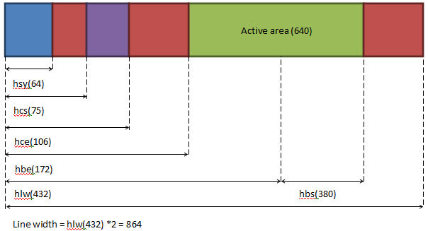
hlw: half line width 432(0x1B0)
hsy: horizontal sync width 64(0x40)
hcs: horizontal sync start to colour burst start 75(0x4B)
hce: horizontal sync start to colour burst end 106(0x6A)
hbe: horizontal sync start to horizontal blank end 172(0xAC)
hbs: horizontal sync start to horizontal blank start 380(0x17C)
*Note: To get the true values (in full lines) we need divide the values stated by 2
With these values we can start to build up a picture of the horizontal line timings (using the values in blue) and the frame size / timings (using the values in green).
Using the above values the horizontal line timings look like this
The two things to note here are, the active area is not given but implied and hbs starts midway through the active area !
Again using the above values the vertical / frame timings look like this
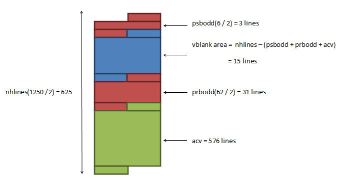
Note that the vblank area is not given but implied.
Measuring the actual signals
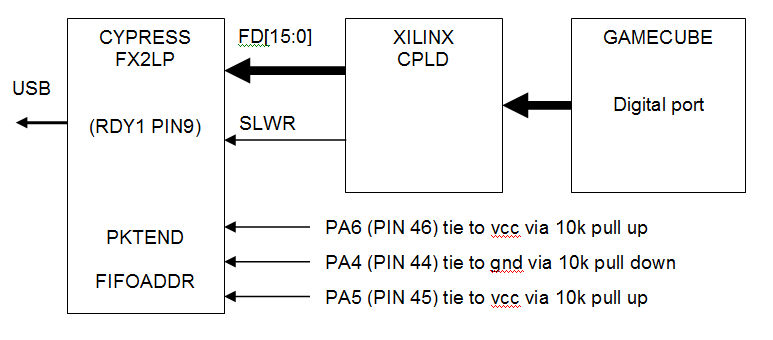
So that's all the "theory" out the way, do the actual measurements match the above diagrams ? Well to answer that question I built my own gc digital port sniffer :-) which was made up of xilinx cool runner 2 development board and a Lcsoft CY7C68013A Mini Board (cypress FX2LP).
CPLD hardware
I configured the CPLD (XC2C256) (here's the VHDL code) to capture the gc digital ports signals (see read_port.vhd) I then used run length encoding to compress the data stream (see rle.vhd) so the data stream was small enough to transmit to the PC. I then wrote some vhdl code (see transmit.vhd) to actually take the rle data stream and transmit it via the cypress fx2lp chip to the PC.
Cypress hardware
I configured the CY7C68013A to used as slave FIFO device this basically means it will take the information on its 16 bit parallel FIFO bus and transfer it to a internal fifo (4kb * 4 (quad buffered)) for automatic USB transmission to a PC whenever the fifo write line is toggled (here's the code I used to configure the cypress device.)
Putting it all together
Here is a block diagram of how I put the gamecube / CPLD / cypress hardware together to create my gc digital port sniffer
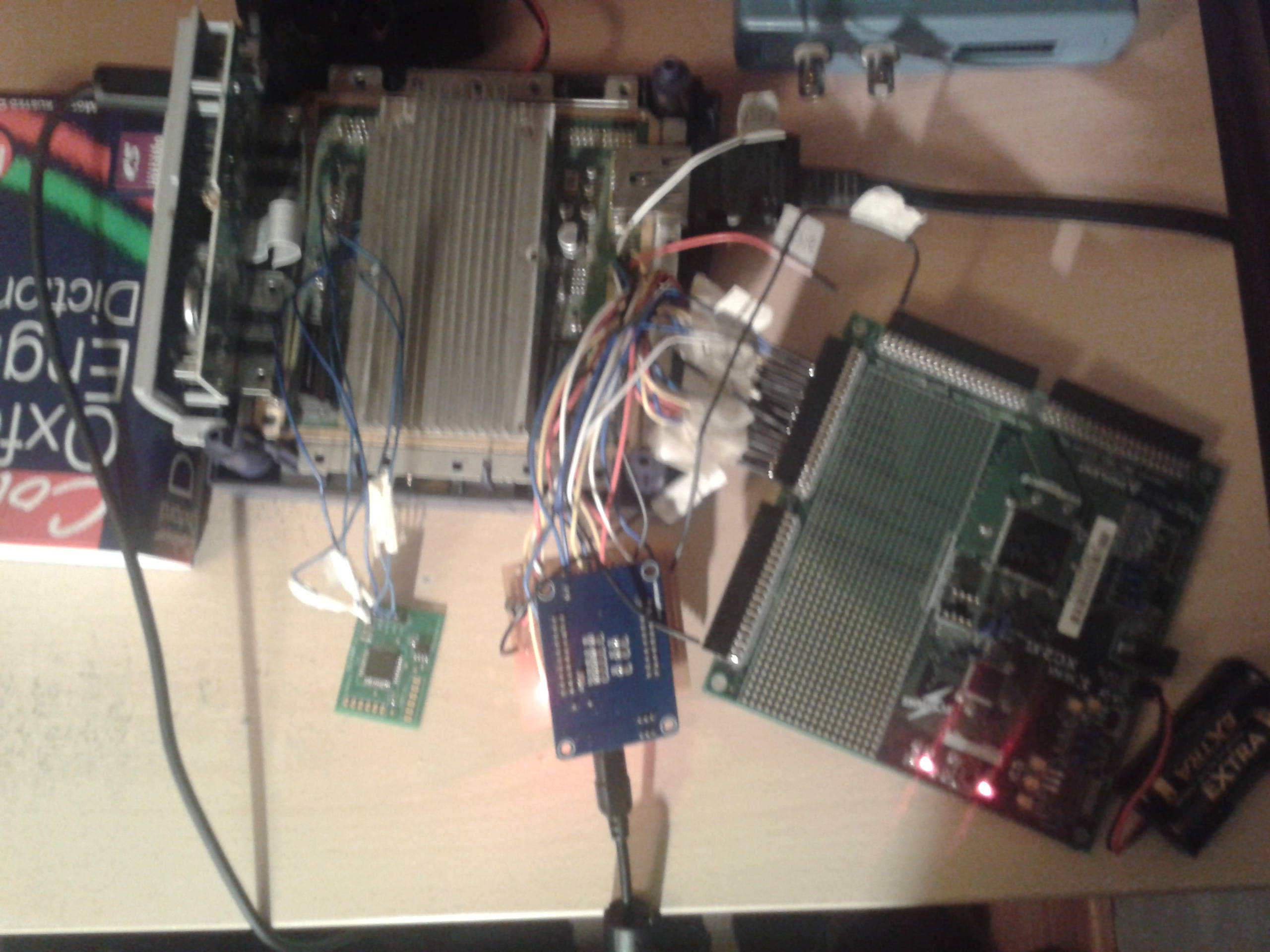
and a pic of my mess of wires sniffer :-)
GC software
As transmitting and encoding the captured digital port data takes time my sniffer works best with large runs of same captured values. So I created this DOL that when executed will just display a black screen of 576p don't think I am going to win any awards for this program :-). However it gives me large runs of black screen space which is perfect for my timing measurements.
PC capture software
Now that I had the hardware to transfer video data to pc via usb I needed to create a pc application to capture this data. This is where I got lazy and re-used the c# program I created for the gc rom dumper. Which itself is based on a cypress demo application (AN63620) Here is the code again :-)
Horizontal results analysis
So after capturing this video data from the gc digital video port you can see that one active horizontal line looks like this
00 2F 00 3F 00 BF 00 0A 00 B7 00 1E 00 BF 00 41 10 80 02 7F 00 BF 00 33
Remember that its RLE and that the VHDL is counting from zero so we always need to add one to the run length. With is in mind the first number is the value in this case 00 2F and the seconds number is the run length 00 3F (actually 0x40 if we add one). What does the value 00 2F mean ? the first part 00 means the digital port is transmitting vsync / hsync flag data. The actual vsync / hsync data is decided in the second part 2F, using the information below
U/V Data Flag Description
Bit 7 C Composite Sync Flag (active low). Refer to
the timing diagrams.
Bit 6 F Field Flag. F = Å"0" for odd-number
fields (Fields 1, 3, . . . ), F = Å"1" for even-number fields (Fields 2, 4, . .
. ).
Bit 5 V Vertical Sync Flag (active low). Refer to
timing diagrams.
Bit 4 H Horizontal Sync Flag (active low). Refer
to timing diagrams.
Bit 3 B Burst Flag (active low). This signal
indicates the location of the color burst. It is active once every line.
Bit 2 K Burst Blank Flag (active low). When
active, color burst of a line should be blanked out.
Bit 1 N NTSC/PAL and M-PAL Mode Flag. N = Å"0" for
NTSC mode, N =Å"1" for PAL or M-PAL mode.
Bit 0 I Interlace/Non-Interface Mode
Flag. 1 = Å"0" for interlace mode, I = Å"1" for non-interlace mode.
We can see that Bit4 is low so this first value 00 2F means we are in hsync and this is transmitted 003F times (actually 0x40 if we add one). Which is the timing defined in hsy (horizontal sync width) so the measured timings match the theory values :-)
Vertical results analysis software
I wrote this little program (yes its got much repeated code I need to add a function call instead but it does the job) to count the number of different vertical lines and after running it on the captured data it outputted
number of horz scan lines is
575
number of half scan lines is
1
number of null scan lines is
2
number of half null scan lines is 1
number of burst blank lines is 4
number of half burst blank lines is 1
number of vert synch lines is
4
number of half vert synch lines is 1
number of burst blank lines is 4
number of half burst blank lines is 1
number of null scan lines is
30
number of half null scan lines is 1
number of horz scan lines is
575
which is a little different from the frame theory values, the measured results reveal that there is an extra area within the vblanking period. The vblanking period of 15 lines is split into
5 lines of colour burst blank
5 lines of vblank
5 lines of colour burst blank.